Technical & downloads
Glossary of Terms:
Joint Types
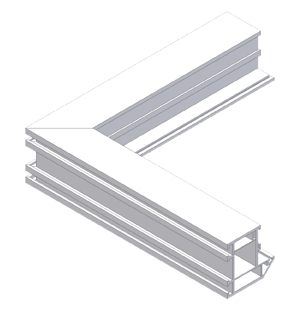
Corner Joint
See Figure 1 of a typical welded outer frame corner joint.
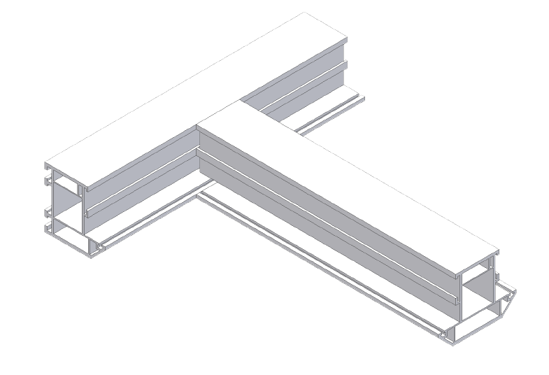
Transom Joint
See Figure 2 of a typical welded Transom joint using outer frame and transom profile.

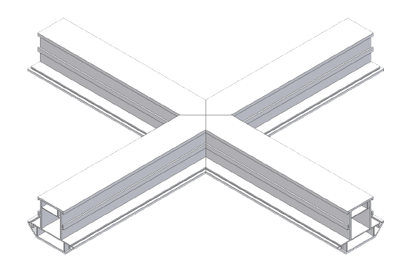
Cruciform / Crucifix / Cross Joint
See Figure 3 of a typical welded Cruciform (or Cross) joint using pieces of transom profile.
An All Welded Window
This means that every joint in a Vinyl/PVC window sash, frame and door has been joined through pvc welding. Good welds create a bond which is stronger than the material itself. A break test should result in the joint splitting away from the weld seam. (i.e. the profile breaks - not the weld)
In All-welded window production the transom and cruciform joints are welded together. To achieve this the outer frame profile usually has a notch cut along its length at 45 degrees (often called a vee ('V') notch), while the transom piece is cut with an arrow head (to marry with the vee notch).
The AVN2 and DGS420 machines are typically used during this stage of fabrication.
See Figure 4. showing the profile pieces of a transom joint - pre-welded.

Figure 5. shows the same transom joint post welding. The HDV series of welders, starting with the 1HDV/140 are used to weld this type of joint.
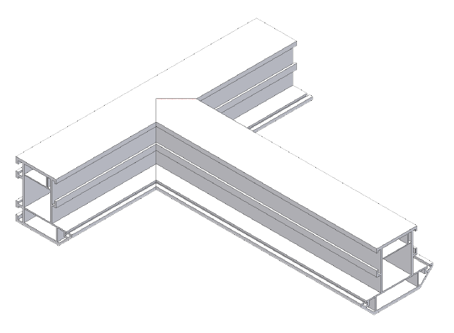
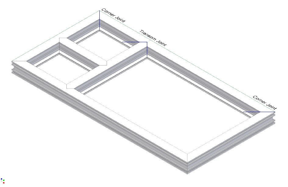
Figure 6. Shows a fully welded window with two corners and a transom labelled.
A Part Welded Window
This means that all corners in a Vinyl/PVC window sash, frame and door have been joined through pvc welding while transom, mullion and cruciform joints have been mechanically joined with a screw and fixture. Mechanical joints generally require the inside shape of the frame to be milled into the end of the transom or mullion in order for the part to 'fit' inside the window.
Figure 7. Shows the transom part with end milling feature to enable it to fit inside the outer frame. An AFV360 End miller is used for this operation.
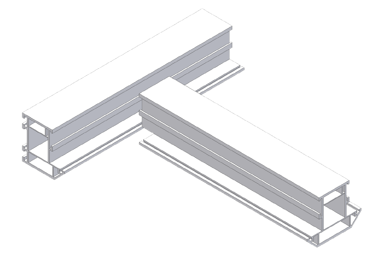
Figure 8. shows the completed mechanical joints after screw fixing.
Burnoff or Melt Loss
The Burn-off is an industry term derived from the fabricator perspective. It means the loss in pvc material at both ends of a profile piece as a result of pvc welding. Normally this figure is 5 or 6mm. (ie: 2.5mm or 3mm from both ends).
From a machine perspective the actual melt loss 'mechanically' speaking is measured perpendicular to the weld seam. There are specific techniques which measure the melt loss in each direction and on each surface of the profile.
Weld Bead limitation
Sometimes called weld seam limitation or knife gap - this represents the setting of the top and bottom knives on a welder which pinch the sprue during the weld process so that a controlled weld seam is created and just visible after cleaning. 2mm or 0.2mm knife gaps are most common. This requirement will be discussed at point of sale and set during the machines manufacturing process.
Reverse Butt Welding
This type of welding is required when making an All welded internally glazed window. To create the necessary transom joints certain frame and transom (or mullion) profiles must be square cut (instead of a 45 degree mitre) at both ends and welded end on end to each other. This is called reverse butt or straight welding. To execute this process a welder capable of reverse butt welding, like the 1HD/02, will need its fences to be set in line with each other (i.e. at a 180 degree angle). As we are now welding across the heater plate as opposed to 45 degree (hypotenuse), the burn-off or melt loss on a 6mm machine is now 2.1mm from both ends (i.e. 4.2mm total loss). Its simply mechanical profile orientation and a case or understanding what burn-off actually means. The same material is lost and the same weld strength is achieved. The difference is how we calculate and interpret burn-off according our window sizes.
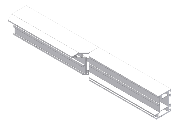
Figure 9. Shows a typical reverse butt weld using outer frame section. A Vee notch has been cut central to the weld seam:
Cruciform or Cross Welding
A mullion profile running across the middle of a frame and a transom profile running down the centre will meet in the middle and create a cross or cruciform joint. To fabricate this joint there are three methods; mechanical, traditional and all-in-one cross welding.
Mechanical means that either the transom or mullion section is cut in half and its ends are milled to fit the shape if the inside of the frame for screw fixing this joint together.
Traditional means the mullion is Vee notched using an AVN2 saw, then welded to make a T joint using a combination head welder like the 1HDV to 4HDV series. A second Vee notch is created on the opposite side of the first and a second transom piece is welding here to complete the cross shape.
Benefits of Cruciform or Cross Welding
All-in-one Cross Welding means that four pieces of profile are arrow headed, placed into a Cross Welder, like the 1HDX and welded together simultaneously. This new method is significantly quicker than the traditional one and, as there are fewer processes, fewer tolerances can build resulting in more consistently square welds which in turn provides in a more aesthetically pleasing finish.
Sprue (or flash)
Sometimes called flash - this is the left over material or waste created during the weld process. The sprue or flash will be removed for functional as well as aesthetic reasons using manual, automatic and/or cnc cleaning machines. Like the EV443/30, EV443CNC, EV470 and EV475 models.
Consumables
This includes items like groove knives, ovolo knives, drill/router bits, saw blades, teflon, cutting fluid, grease, oil, lubricant, refuse sacks, which by their nature will be consumed or wear over time and require replacement to ensure your equipment performs to its optimum.
Front Line Spares
These normally include items of electronics which are considered useful to have on the shelf in case of emergency. Like a mini repair kit these items can be used for speedy faulty diagnosis and therefore help reduce downtime on machinery.
PLC Unit
Stands for 'Programmable Logic Control' Unit - which represents the industrial computer unit found inside most modern industrial machines.
HMI Unit
Stands for Human - Machine - Interface and refers to the display screen which operators use to enter and view data relating to the machine in question.
ome HMIs are just display terminals, others store machine data, and combined units can have a plc built-in
CNC Control
Stands for Computer Numerical Control - The means the position of a moving head or axis can be programmed electronically via a HMI to a very high degree of accuracy.
Electrics and weights
| MACHINE | VOLTS | PHASE 50 CYCLES (HZ) | TOTAL AMPS (*EARTH+NEUTRAL) | MAX BAR PRESSURE | LITRES PER CYCLE | CONNECT POSITION | WEIGHT | LENGTH | WIDTH | HEIGHT |
|---|---|---|---|---|---|---|---|---|---|---|
| MGS350 | 220-240 | 1 | 14.5 | 7 | 10 | CENTRE REAR | 115KG | 760 | 620 | 650 |
| MGS350 | 380-415 | 3 | 7 | 7 | 1 | CENTRE REAR | 115KG | 760 | 620 | 650 |
| DGS350/400 | 380-415 | 3 | 15 | 7 | 35 | LEFT REAR & RIGHT REAR | 500KG | 4250 | 900 | 1700 |
| DGS350111 | 220-240 | 1 | - | - | CENTRE REAR | |||||
| Extractor | 380-415 | 3 | 5.5 | CENTRE REAR | ||||||
| DGS420 | 380-415 | 3 | 9.90* | 7 | 200 | LEFT REAR | 600KG | 4230 | 600 | 1400 |
| CRD1201 | 380-415 | 3 | 2* | 7 | 5 | CENTRE REAR | 160KG | 800 | 570 | 1500 |
| CRD1201W | 380-415 | 3 | 2* | 7 | 5 | CENTRE REAR | 160KG | 800 | 570 | 1500 |
| WSF442 | - | RIGHT REAR | 75KG | 450 | 750 | 1550 | ||||
| AVN2 | 380-415 | 3 | 6* | 7 | 10 | RIGHT FRONT | 110KG | 540 | 1000 | 1150 |
| SRS2500 | 380-415 | 3 | 2 | - | - | CENTRE REAR | 65KG | 520 | 750 | 610 |
| AS3M/AS1A | - | - | - | 5/6 | 100 | CENTRE REAR | 36KG | 500 | 500 | 775 |
| AFV360 | 220-240 | 1 | 8 | 7 | 10 | CENTRE REAR | 36KG | 440 | 520 | 440 |
| EKS432(MAN) | 220-240 | 1 | 9 | 7 | 20 | RIGHT FRONT | 288KG | 800 | 900 | 1250 |
| 1HD | 220-240 | 1 | 9 | 7 | 20 | RIGHT REAR | 350KG | 800 | 900 | 1900 |
| 1HDX | 220-240 | 450KG | 600 | 960 | 1800 | |||||
| 2HD | 380-415 | 3 | 9.00* | 7 | 40 | RIGHT REAR | 600KG | 3015 | 560 | 1700 |
| 2HD1V | 380-415 | 3 | 9.00* | 7 | 40 | RIGHT REAR | 600KG | 3015 | 760 | 1925 |
| 3HD | 380-415 | 3 | 9.00* | 7 | 80 | RIGHT REAR | 1100KG | 4000 | 760 | 1925 |
| 4HDV | 380-415 | 3 | 18.00* | 7 | 120 | RIGHT REAR | 1430KG | 4000 | 760 | 1925 |
| 4HD-QUAD | 380-415 | 3 | 20.00* | 7 | 120 | RIGHT REAR | 1250KG | 4000 | 2000 | 3000 |
| EV345 | - | - | - | 7 | 20 | CENTRE REAR | 30KG | 700 | 520 | 520 |
| EV443 | 380-415 | 3 | 3.60* | 7 | 40 | CENTRE REAR | 420KG | 980(2100) | 860(1400) | 1545 |
| EV443CNC | 380-415 | 3 | 3.60* | 7 | 40 | CENTRE REAR | 420KG | 980(2100) | 860(1400) | 1545 |
| SCT9 | - | - | - | 7 | 30 | CENTRE REAR | 75KG | 800 | 900 | 1200 |
| EV470 | 380-415 | 3 | 6.00* | 7 | 20 | LEFT REAR | 750KG | 1960(2250) | 950(3400) | 1950(1950) |
| EV475 | 380-415 | 3 | 18.00* | 7 | 120 | RIGHT REAR | 1250KG | 3460 | 2520 | 2300 |
| MGS250 | 220-240 | 1 | 5 | - | - | CENTRE REAR | 20KG | 500 | 500 | 500 |
| SFT300 | 380-415 | 3 | 3.00* | 7 | 20 | RIGHT REAR | 250KG | 4000 | 2050 | 2200 |
| SFT300 | 380-415 | 3 | 3.00* | 7 | 20 | RIGHT REAR | 300KG | 3000 | 1300 | 900 |
| GLS181 | 220-240 | 1 | 13 | 7 | 20 | RIGHT FRONT | 200KG | 1000 | 700 | 1200 |
| GLS185 | 380-415 | 3 | 6* | 7 | 4 | RIGHT REAR | 110KG | 540 | 1000 | 1150 |
| G180220 | 220-240 | 1 | 13 | - | - | LEFT REAR | 110KG | 3000 | 250 | 100 |
| VKP-3 | - | - | - | 7 | 50 | CENTRE REAR | 180KG | 3000 | 600 | 1900 |
| PBM1 oven | 220-240 | 1 | 4 kW | - | - | CENTRE REAR | 150KG | 3700 | 500 | 900 |
| PBM1 table | 220-240 | 2800 | 1830 | 900 |
KEY - CONNECTION POSITION
* EARTH + NEUTRAL REQUIRED
LR - LEFT REAR
RR - RIGHT REAR
CR - CENTRE REAR
LF - LEFT
FRONT
RF - RIGHT FRONT